Hexagon Manufacturing Intelligence’s metrology software tools embrace manufacturing excellence, improve efficiency and ensure reliable product delivery. In our new PC-DMIS software release, PC-DMIS 2019 R1, we introduce the new function ‘GD&T Selection from Capture’. This feature is an industry world first from Hexagon.
This tool is amazing… This is going to change the way I program.
– Jim – PC-DMIS user, Aerospace industry
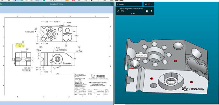
GD&T Selection in PC-DMIS allows you to quickly create measurement routines from dimensions embedded in a 3D CAD model. Until now, when using older parts that still require coordinate measuring machine (CMM) programming, the process of creating a measurement routine has been a lengthy one. ‘GD&T Selection from Capture’ uses optical character recognition (OCR) technology to automate the addition of product manufacturing information (PMI) data into your programs. This function efficiently connects 2D print and 3D CAD models, delivering many benefits including:
1. Faster creation of measurement routines
This function dramatically decreases the amount of time required to program a new measurement routine. With GD&T Selection from Capture, a measurement routine is automatically generated as dimensions are embedded into the model.
2. Ability to use existing part prints
GD&T Selection from Capture uses information in part print as the source of the PMI Data. This means that even much older parts can utilise this function simply by importing a PDF copy of the part print into PC-DMIS.
3. A simplewidget that guides the user through creating features in PC-DMIS
You are guided through the process of selecting and embedding data into feature(s) in the program, simplifying your experience and eliminating the need for a high level of expertise.
Sweet new feature!
– Eric – PC-DMIS user, Aerospace industry
Using the GD&T Function
First, simply import a PDF image of the part print to PC-DMIS. Then box select a dimension and assign this to a feature in the CAD model simply by clicking. This process is then repeated for each set of dimensions and can even be utilised where a dimension refers to several identical features. Duringthis process the measurement strategy and path lines are generated – amendments can be made at this stage if necessary. Tolerance information is automatically imported from the print, eliminating any chance of input errors as well as reducing processing time.
The use of this function can be extended using ‘GD&T Selection from File’. In this instance PC-DMIS reads the whole file, automatically selecting and highlighting each dimension in turn. This feature guides you through the process of selecting each feature and generates a measurement routine automatically.
GD&T selection with PC-DMIS is changing the shape of routine creation. Watch a video tutorial on this function below.


