Reverse engineering is a growing need across nearly all advanced manufacturing industries, especially in situations where product lifecycle changes for new and old parts can lack complete design drawing history, among other issues. That means part reproductions that lack CAD models or 2-D drawings, and/or modifications have been introduced over time. By creating a 3D virtual model from an existing physical part, manufacturers can create a CAD model that can enable accurate production.
Everything from analysis of product functionality and subcomponents, to cost estimation and even patent infringement avoidance can drive reverse engineering. Companies and shops of all sizes and acrossindustries utilize reverse engineering to transfer a physical product or part into the digital realm with some of the more prominent industries including:
- Automotive Industry (Sheet metal die tool design and part prototypes as well as clay model designs)
- Aerospace Industry (As-built component digitization for assembly process, legacy component archiving and even full sized aircraft analysis)
- Healthcare (medical device as well as replacement anatomy structures among others)
- Historic Preservation
Goals and level of needed accuracy are clearly the first decisions when considering reverse engineering. This is closely followed by an understanding of the reverse engineering tools that are necessary to make it possible.
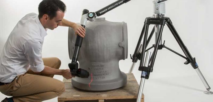
Handheld measurement tools such as calipers and other manual devices are quickly fading from use across most industries. This is due to the complex geometries of many parts and products , tighter production cycles and the need for cost containment make them unsuitable. The accuracy and precision required today can only be delivered via the use of integrated 3D scanning technologies with PCMMs.
The scanner itself must be capable of scanning the widest line possible with the highest accuracy in terms of the number of points that it captures per line. This should ideally scan multiple thousands of points per scanningline path to ensure that accuracy. Other aspects like a maximum standoff distance are important to ensure that the scanner can reach into deep crevices of the part and deal with irregular geometries effectively.
The measured data, usually represented as a point cloud is captured by the laser and transferred to a computer via point cloud scanning software. This software enables visualization and
manipulation of the scan so that it can be transferred to a CAD program to create working drawings for production or prototyping.
This software should provide several features to enable proper visualization of points for assessment and manipulation without any loss of detail. This topological information is processed into an STL file so that it can be used to create a fully parametric model using an advanced CAD package to get the final deliverable.
While there are numerous reverse engineering tools on the market, they are not all created equal, nor are they intended for every type of reverse engineering project. By having a clear definition of the level of accuracy needed as well as budget and time considerations, businesses can determinewhat is the best solution that will deliver the highest ROI for the product manufacturing lifecycle.


