Easy modification, accurate representation, and built product insights are the principle interests to consider when instituting a rapid prototyping process. While achieving those goals starts with an understanding of the approachesand the tools directly involved in making that process a reality, it also involves an understanding of the potential pitfalls and how to avoid them.
Rapid Prototyping (RP) can be defined as a group of techniques used to quickly fabricate a scale model of a part or assembly using three-dimensional computer aided design (CAD) data. It uses span tolerance testing, male model tooling, and even finished products as part of a larger assembly in cases of complex parts integration.
From small shops to multinational manufacturing interest, the reasons for utilizing rapid prototyping are as diverse as the companies and industries that leverage this process, but often includes:
- Increasing effective communication
- Decreasing development time
- Decreasing costly mistakes
- Minimizing tooling and engineering changes
The basic methodology for all current rapid prototyping techniques can be summarized as follows:
- A CAD model is constructed, then converted to STL format where the resolution can be set to minimize stair-stepping.
- The rapid prototyping machine processes the STL file by creating sliced layers of the model.
- The first layer of the physical model is created. The model is then lowered by the thickness of the next layer, and the process is repeated until completion of the model.
- The model and any supports are removed. The surface of the model is then finished and cleaned.
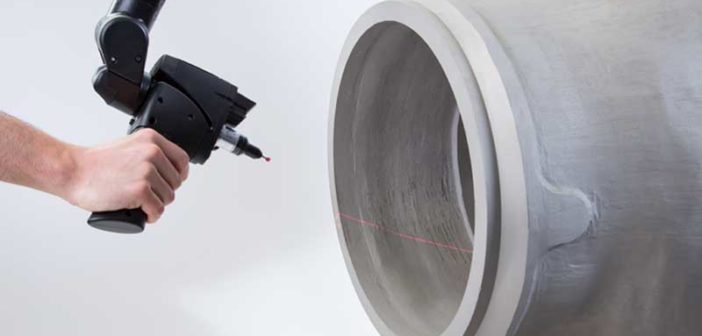
While the benefits can clearly be numerous, the prototyping process can have inherent challenges. The high cost of machines, skilled labor, and in most cases the limits of one prototype at a time as well as potential for rework due to tolerance inaccuracies. These challenges make it difficult to see fast ROI, but there are ways to optimize the process. Whether it is a new design or a reverse engineering need, making 3D laser scanning part of the rapid prototyping process can bring major efficiency gains.
In both new and reverse engineered prototyping, tolerance accuracy is paramount, which can be problematic even with highly accurate machines. The pitfall for manufacturers and design shops is that it can be challenging to verify the dimensional tolerances as defined by the CAD design and that of the rapid prototyped model. This is where the latest 3D laser scanners can enable fast and accurate scans of original parts for developing the CAD design for the prototype and ensure that subsequent prototypes can be quickly scanned to ensure that it meets tolerances.
While rapid prototyping can require a significant learning curve, today’s laser scanners enable operators to get up to speed quickly. Ultimately, this shortens the prototyping as well as the eventual manufacturing process as it ensures greater accuracy, less scrap and faster production cycles that meet deadlines that have financial consequences.


